Theoretical aspects:
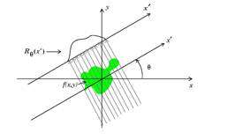
The Radon Transform of an image is represented by a mathematical function f(x,y), which can be defined by a series of line integrals using f(x,y) at different distances from the origin .
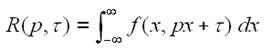 From a mathematical point of view, the Radon Transform is defined by
:
From a mathematical point of view, the Radon Transform is defined by
:
where:
 p and τ represent the slope and the lines
intersection.
p and τ represent the slope and the lines
intersection.
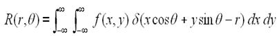
Is a more direct method of applying the transform, which is defined by using the Dirac Distribution, where τ represents the rotation angle from the Ox axe and r represents the projection on the Ox axis. The data acquisition in medical techniques like the MRI, CT și PET scanners require an equivalent method and the experimental data is similar to the one needed by the equation above.
Used materials and data acquisition
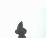
For the acquisition of data we use a screen in front of which we place the object on a disc rotated by a step by step electric motor ( 48 steps ).
The web camera is placed perpendicularly to the object and has the role of capturing one image for each step of the motor. Using this method we obtain a 2D representation of the object from 48 different angles.
The first step in data processing is transforming the picture from a RGB format in a Grayscale format to obtain a greater contrast between the object and the background. This is accomplished using the formula:
Gray=0.3*Red+0.59*Green+0.11*Blue, for each pixel.
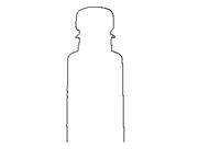
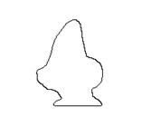
The necessary information for the object reconstruction is the shape, the coordinates of each pixel on the object’s outline, relative to the rotation axis.
Obtaining the contours from each of the 48 pictures is done by erasing pixels from the object’s interiour untill the width of every line and curve on the outline is of one pixel. The resulting set of lines and curvev represents the frame of the object.
![]()
![]()
For obtaning the frame of the object we use the following algorithm: browse the pixel matrix of the initial picture from left to right and from top to botton and test the colour level. The processed image will contain only the pixeles that are on the borderline between black an white.
In terms of hardware the scanner is based on two major components:
- A USB webcam, with a minimum VGA resolution ( 0.3 megapixeles – 640x480 ) and a CMOS light sensitive sensor with contrast and brightness settings.
- A rotating disc powered by a step by step motor controlled by a 18F4550 8 bit Microcontroller, with an USB port and a motor driver ( L298H ) – H-bridge. The motor can be controlled by 2 buttons placed on the PCB or trough the USB. At the moment drivers are only available for Windows Xp.
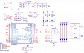
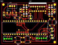
Schematic PCB
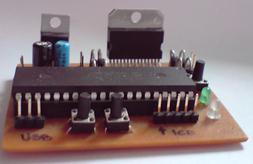
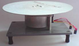
The populated PCB The disc and the 48 step motor
The entire device is powered by an external 6V direct current power source, and the webcam is powered through the USB ( 5V ).
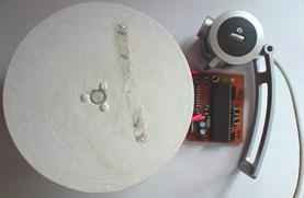
The 3D scanner
For software development we used a combination of Microsoft Visual C++ 2008, Delphi 7 and MATLAB programming languages for computer processing and Microchip MPLAB, Microchip C18 for the PIC Microcontroller’s programming.
The main programs, the webcam image capture, the program that moves the rotating disc, are made in Delphi. In Visual C++ we have made the processing program that obtains the outlines of the object and the Radon transform for the images and the 3D rendering is made in MATLAB.
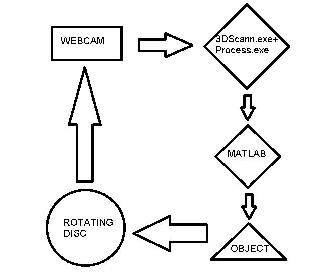
Process schematic/ Operating Principle
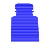
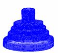
Results:
The following images ilustrate some of the results:
![]()
![]()
![]()
![]()

![]()
![]()
Here are the links to the output objects of the application:
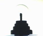
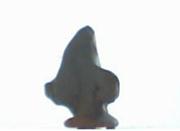
- Figure 1 - Coconut decoration
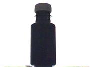
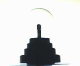
- Figure 3 - Printer Ink Bottle
Findings and conclusions:
The research had the expected result, the algorithm works for convex objects and can be optimized to detect certain cavities, for example it can detect the cup handle without filling the gap.
The precission with which we obtain the 3D representation of the object depends on the following factors: webcam rezolution, CMOS sensor sensitivity and the number of steps made by the electrical motor. Another optimization can be made by porting the source code in C++ and OpenGL( increased processing speed).
The tests were made on a 320 x 240 rezolution, and a 48 steps motor. An increased rezolution would generate more reference points on the X and Z axis, and an increased number of steps would improve the Y axis rezolution. Related to the stepprer’s torque, it would be best if it had reduction so we can minimize the wobbling of the object on the disc, thus reducing capturing errors.